Flashing Tasmota on Smart Plugs via Serial
Which piece of hardware makes “smart things” actually smart?
It turns out that for many of them, including smart plugs, it is the same ESP8266 chip, a low-cost, wifi-enabled microcontroller that has become very popular with tinkerers, along with its more capable ESP32 successor.
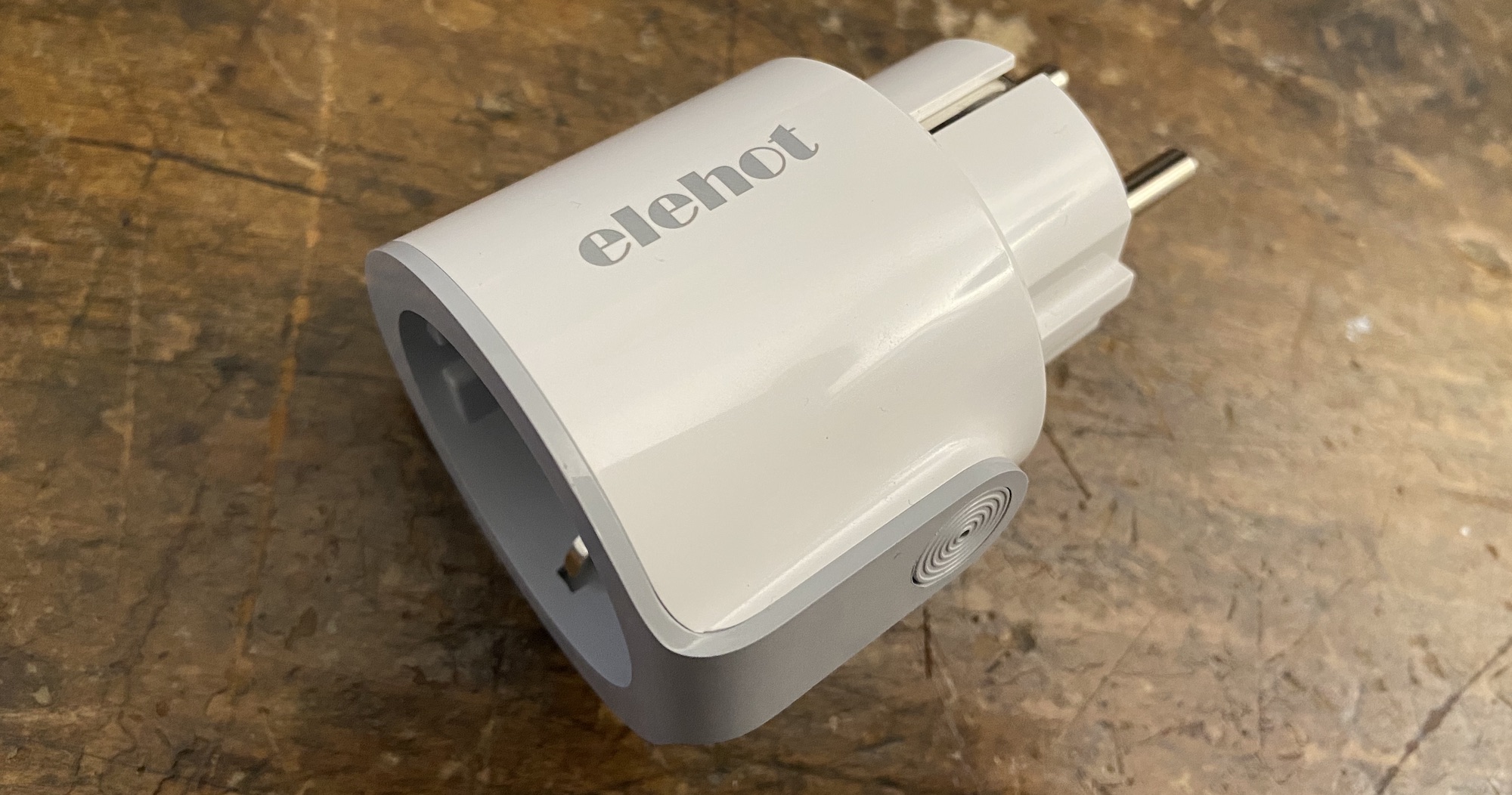
I recently bought a 4-pack of generic smart plugs (“Elehot AWP16L”) for my new house in order to save energy by turning devices on and off automatically and monitoring their overall power consumption. They became unavailable on Amazon shortly after I bought them at a steep discount, but they are similar to a lot of devices originally designed by Tuya and then white-labeled by other brands. When buying any of these generic plugs, just make sure that they are based on the ESP8266 or even better, that they have already been reported by the community as compatible!
Most of these devices connect to the Internet via Wi-Fi in order to work properly. They interface with apps like Smart Life or with the assistants from Google, Amazon or Apple. This is a non-starter for me, because my “smart home” network is completely offline by design. The last thing I want is having my plugs call home to whomever their former master was…
Enter Tasmota, an amazing open source firmware for ESP8266-based devices! Flashing it on the smart plugs would allow me to take full control of them and make sure they behave properly in my offline network.
The easiest way to do that is over-the-air (OTA) via Wi-Fi with tuya-convert. This script actually uses a vulnerability in older Tuya firmwares which allows them to be remotely flashed with a new firmware like Tasmota. Unfortunately, Tuya patched the exploit in late 2019 and for most devices manufactured since then, OTA update will not be an option until a new workaround is found.
But fear not, we still have a way of liberating our poor plugs: a serial connection! This involves interfacing directly with the ESP8266 via physical wires and using an USB-to-Serial adapter to flash the firmware. This sounds scary but what follows is a step-by-step walkthrough of how I did it, roughly following Tasmota’s instructions! There are a few bits specific to the model I got but the rest applies to all ESP8266-based plugs.
Step 0: Hardware prerequisites
- ESP8266-based smart plug
- Tools to open it up (screwdriver, knife, …)
- USB-to-Serial adapter and wires (Amazon, Aliexpress)
- Soldering iron
- A computer with Python installed
Step 1: Open up the plug
This part was actually harder than expected! After removing the screw inside the socket I had to use a knife to pop 3 clips in the seam of the plug. Watch your fingers!
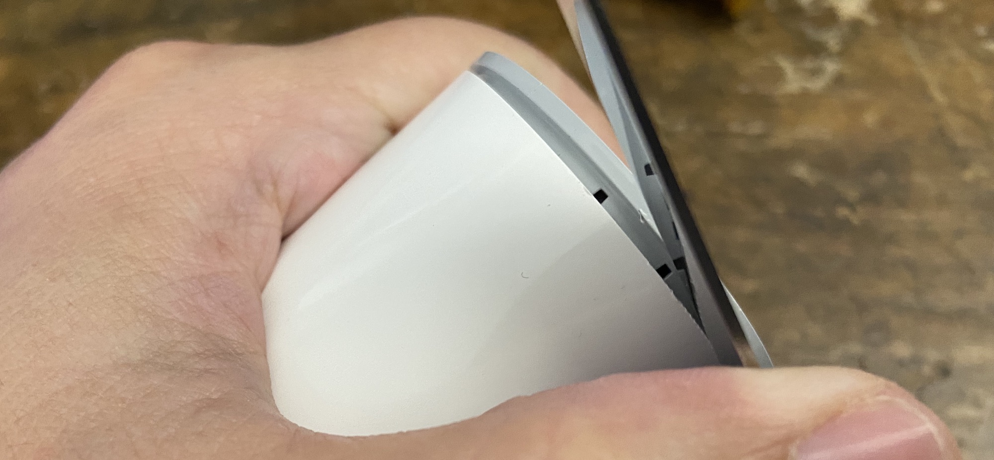
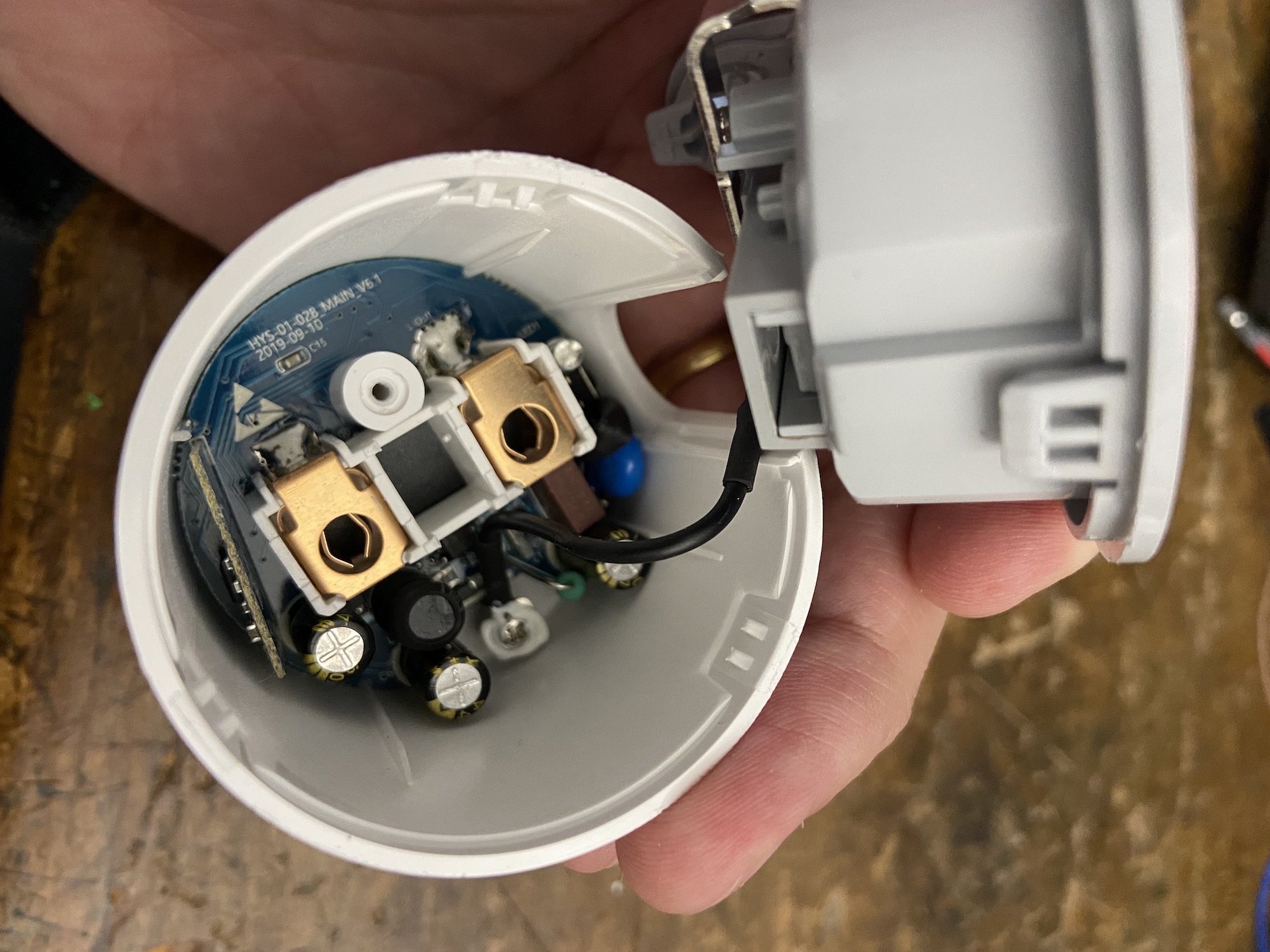
Once this is done you can push on the male side and the whole board will come out. This goes without saying, but don’t plug anything while it is opened up…
Step 2: Identify the right pins
There are slight differences between ESP8266 boards and their pins will not always be mapped to the same functions. This mapping is called a pinout.
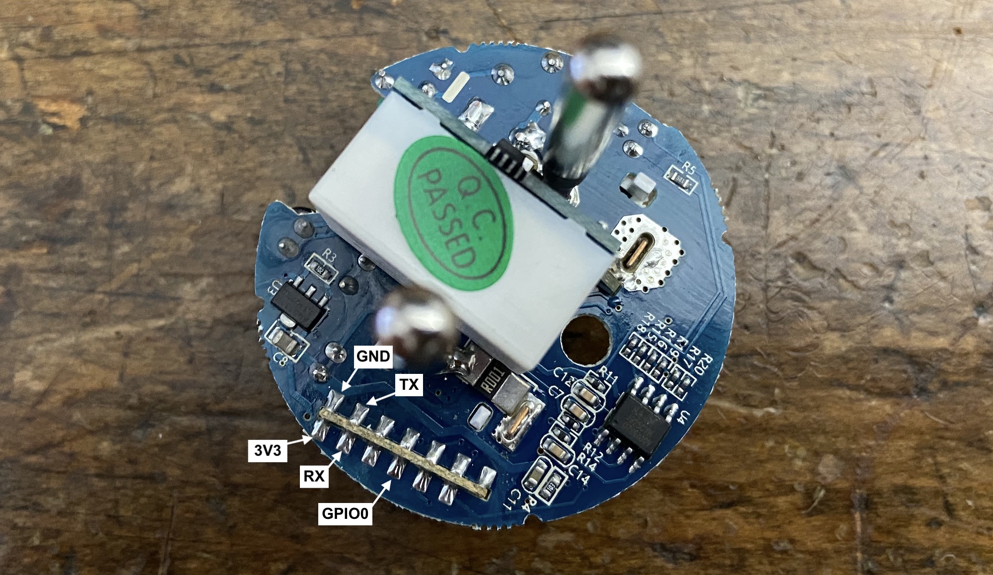
The best way to find the pinout of your specific board is to google any reference you can find written on it. In my case, it led me to this comment on GitHub which helped me build this pinout:
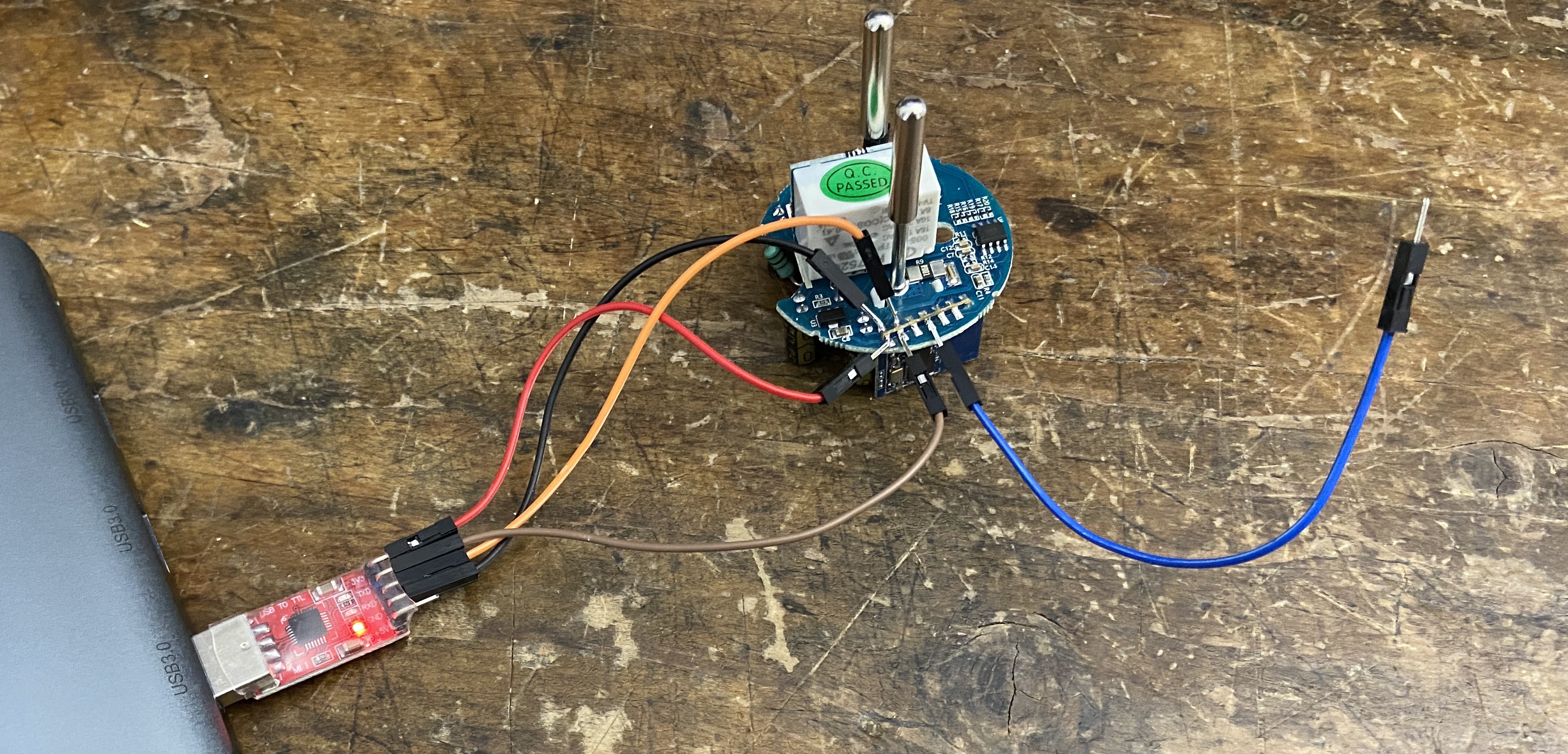
Step 3: Connect the wires
Some board layouts might allow a solder-less connection but this was not the case here. So I reached out for the soldering iron and this was the (amateurish) result:
I did not need to add any solder to make the connections, just melting the existing drop and inserting the wire quickly into it was enough. This is temporary after all!
Step 4: Make sure the serial connection works
Before writing anything to the chip, let’s try reading from it first! It is a good way to make sure everything works properly before risking to brick the device.
You should make sure your USB-to-Serial adapter works properly. On macOS I needed to install these drivers for my CP2102-based one. Once it is done, you should have a device named /dev/tty.SLAB_USBtoUART (look for it with ls /dev/tty*).
Then, connect the GND and 3V3 wires to the adapter, but make sure to connect the RX pin from the adapter to the TX pin of the board, and inversely. Leave the GPIO0 hanging for now.
If you connect everything as-is, the ESP8266 should run with the stock firmware, on the 3.3V provided by the USB adapter. In my case I could see the LED blink.
What we want to do now is boot into “Flash Mode”. This is done by connecting the GPIO0 wire we left hanging before to the GND pin (also called “short to ground”), while the chip is booting up . I used one hand to keep them touching for a few seconds, and the other one to plug the USB adapter into my computer. The LED should not blink anymore in this mode.
At last, you should be able to read some data from the chip from the command line! After installing esptool, you can run:
$ esptool.py flash_id
esptool.py v2.8
Found 5 serial ports
Serial port /dev/cu.SLAB_USBtoUART
Connecting....
Detecting chip type... ESP8266
Chip is ESP8266EX
Features: WiFi
Crystal is 26MHz
MAC: XX:XX:XX:XX:XX:XX
Uploading stub...
Running stub...
Stub running...
Manufacturer: 68
Device: 4014
Detected flash size: 1MB
Hard resetting via RTS pin...
Step 5: Flash Tasmota
There are a couple ways of flashing Tasmota once the serial connection is established. The easiest one is to use Tasmotizer, which is basically a GUI on top of esptool.
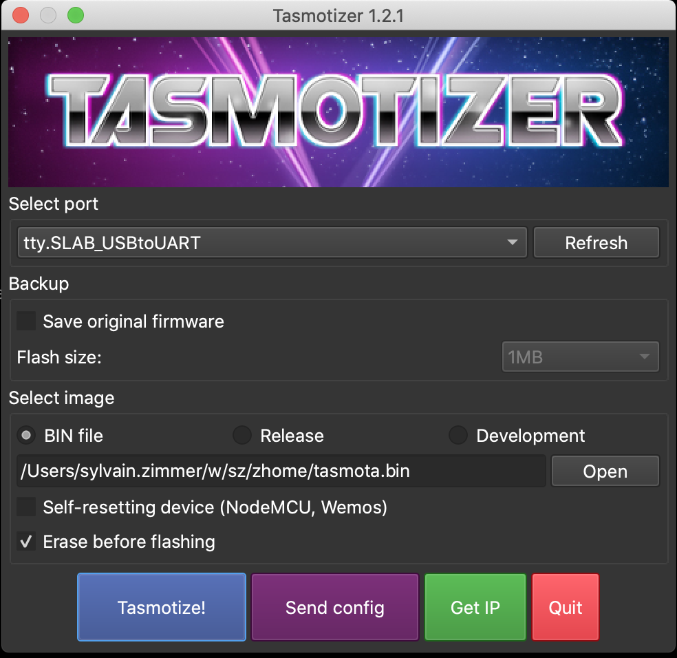
Regardless of the tool, you need to pick a build of Tasmota. In most cases, you should just use the latest tasmota.bin.
Step 6: Configure Tasmota
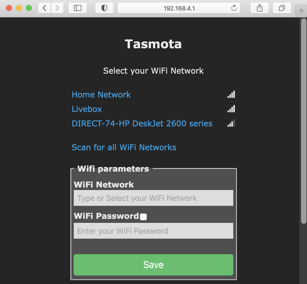
Once you reboot (you can just unplug/plug the USB adapter from your computer), Tasmota will be running on the ESP8266 instead of the factory firmware! You should see a new Wi-Fi network named tasmota_XXXXXX-#### and once connected to it, just open http://192.168.4.1 in a browser to get to the Tasmota web UI:
That’s right, you are now browsing on a web server embedded in a power plug…
Now you need to configure the plug for your local network. After entering your Wi-Fi credentials and reconnecting to the plug via its new IP address on your local network, you will need to tell the generic Tasmota firmware about the specific pinout and features of your device.
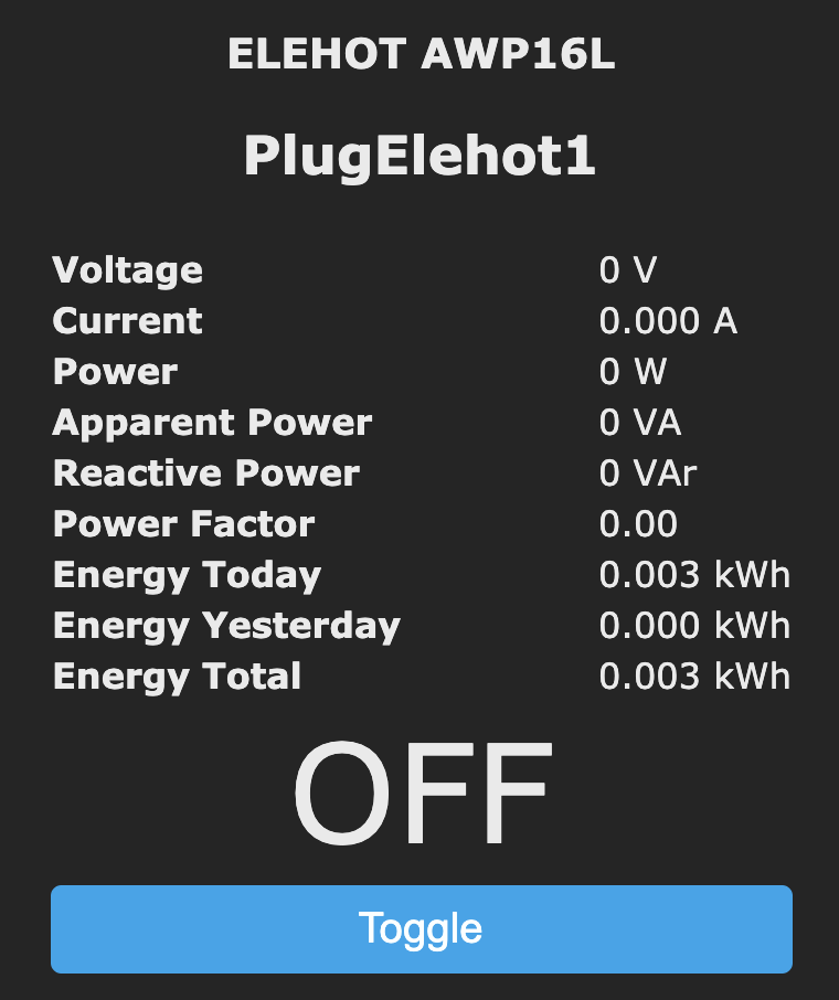
This can either be done manually in the web UI, or with helpful templates provided by the community. One already existed for my model, so all I needed to do was to copy and paste this bit of JSON in the Configuration > Configure Other menu:
{"NAME":"ELEHOT AWP16L","GPIO":[0,0,56,0,0,134,0,0,131,17,132,21,0],"FLAG":0,"BASE":45}Do not forget to check “Activate”! After a reboot, you should now be able to toggle the plug from its web UI:
Step 7: Put it back together
Now it is time to put it back in one piece! First, un-solder the wires and then screw the board back in the plastic shell.
Once finished, you should test that the ground line is still going from one end of the plug to another with a multimeter if you have one. This helped me detect an issue with one of my 4 plugs, because some white paste had ended up under a screw holding the ground connector inside the plug.
Of course, the real test is plugging it into the wall and making sure that you can still access the web UI!
Step 8: Use it in your network
After all, connecting the plug to home automation is the reason we went to all this trouble in the first place!
The details will vary depending on your home setup, but most people will either:
- Configure MQTT on the plug and control the plug via the Tasmota MQTT API or via an integration into a home automation system like Home Assistant.
- Use Tasmota’s ability to flash a new firmware from its web UI to install a completely different one, like ESPHome.
What’s next?
If you want to avoid soldering or even flashing, you can actually buy smart plugs that come already loaded with either Tasmota or ESPHome! I ordered a pack of Athom ones and will report back when they arrive.
Meanwhile, I am already using the first 4 plugs to turn off most appliances when I leave the house and toggle my air filtering system depending on the output of multiple air quality sensors… More on these soon in a follow up post!